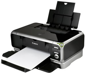
It’s selectable via the driver or a front button. This also limits dust intake, expands capacity to 300 sheets and acts as an alternate source for envelopes, headed or photo paper. This is spoiled slightly when the input tray is open, but a second tray at the base can be used exclusively. The side-mounted cables make it fit flush with the wall. First there are the looks, matching those of the pricey iP8500, which costs almost four times more. It's likely apiece of paper or dirt inside the forked ight barrier which controls the head positoning.We first saw the iP3000 back in issue 121 and were amazed at what was on offer for the price.

As you are basically turning a non functioning colour printer into a BW printer. This is for anyone who mostly prints black text. If you are like me and want to screw the last ounce out of every device this will work with most Canon Pixma range as the ink cartridges are the same size for small black and colours. Hey presto can now print in black!! It also helps to set printer preferences to high quality. After printing a few "green blocks" to purge old colour still in head. I select font colour to standard green (the default green in MS Office). I had spare black cartridges (smaller size) so I replaced Cyan Magenta and yellow cartridges with black cartridges. If all else fails it is probably the printer head. This is a diagnostic programme for your printer. Wash print head luke warm water dry carefully,ĭownload and use canon My printer utility from their site. If everything works on your Canon Pixma printer except black? I am not sure if this is the right place for this fix I've found. Step 10: Reassemble the printer and retest. Step 9: Tighten the 4 mounting screws without When seated correctly, the gap will no longer be present. The tip of the white plastic guide should sit slightly inside the Step 8: Re-seat the white plastic guide so it sits flush against the Chassis.

Step 7: Loosen (do not remove) the 4 mounting screws (the mounting screws can be found behind the Step 6: Disc connect the appropriate cables and remove the Logic Board from the Chassis. Even if the gap is not visible, complete the steps below.

Step 5: Inspect the ASF section of the Main Unit for a gap between the white plastic guide and the Chassis. Step 4: Turn the Main Unit over (upside down) and place on work surface. Step 3: Remove the Main Unit from the Bottom Case. Step 2: Remove the 4 mounting screws from the Chassis.

Step 1: Remove the Left and Right Covers and the Main Case Unit (main cover) When this occurs, the gears cannot rotate properly causing a grinding noise and 5 alternating blinks (SFP) or #356


 0 kommentar(er)
